I’d like to share some info on the procedural pipework I’ve been working on. This stems from a desire to start building complicated industrial facilities that a game idea I have will need. I’ll go into some of the details below, and then in another thread expand on the grander plans for them.

2 Likes
The main pipework components I have so far are:

- Adaptor - size change
- Elbow - right angle turn
- Manifold - multiple side ports, optional end or continue
- Offset - shift between points on two parallel planes
- Programmable - carry out a sequence of offsets, turns
- Straight - simple straight pipe section
- Tee - Straight section with a single (generally smaller) side port
- Wiggle - Straight section with a centre offset section
- Valve - Gate valve for interrupting flow, selectable handle
From these individual components many configurations can be made, and to assist I wrapped them all in a set of procedures designed for building modular pipework. Each piece has config paramaters passed through which includes the location of each output point, ready for the next piece to be ‘bolted on’.

The procedure for this, showing the ‘connection flow’ used:

1 Like
Pipe termination can be selected from a variety of choices:
- Seamless
- Seamless with inside
- Flange, no bolts, with inside
- Flange, bolted (heads)
- Flange, bolted (nuts)
- Blanked flange
- Sealed
It’s worth noting here that each configuration has different use cases, and geometry for parts you won’t see are not generated. E.g. if you bolt a pipe to something you wouldn’t see the insides. For individual components however, if one end allow you do see inside then it will override the hiding from another end that doesn’t need it. This way we can have nice looking unattached ends but still reduce the cost when possible.

Let’s start digging into the procedures. For the straight section we have this so far:
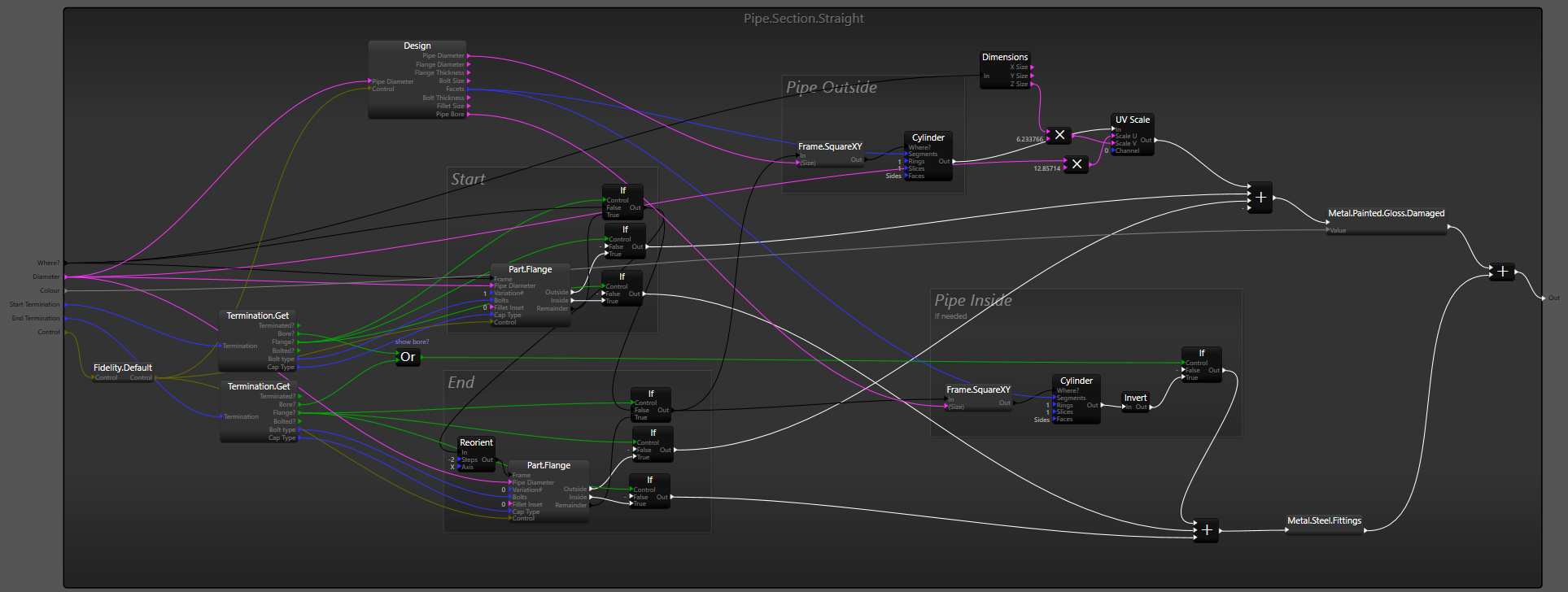
A couple of things going on worthy of note:
- A selection of design parameters are all based on the pipe diameter (Design proc).
- Similarly a number of termination controls are derived from the end type (Termination.Get).
- The termination switching may or may not split off a section to build the flange.
- A straight section is a fairly simple piece of geometry (Cylinder op).
Let me know if you want some more detail of any of the procedures. We’ll have a look at Part.Flange while we’re here though.

Again, the pipe Design parameters are expanded out based on the pipe diameter, and feed into the various sections and optional parts. The various components are enabled and disabled with the If (Seg) operator, either choosing between two different bits of geometry or simply enabling/disabling one.
The ring of holes is a sub procedure called Part.Flange.open, that used a collection of ellipses to build a shape extruded as a flat plate.

A sub-procedure collects together the holes to cut into the main extrusion, and also any geometry that should appear within them. The reason this is done separately and not just with the main extrusion is that the outer surface of the flange needs a different material than the inner surface of the holes (and pipe).

NOTE: This procedure is using the old form of the Extrude operator. This has been superceded with an improved version where you compose the shape first via a number of shape/combine operators, and then feed it into the extrude (rather than just a shape + holes inputs). It’s a lot more powerful and overcomes some problems with certain shapes that you wouldn’t be able to construct otherwise (e.g. islands in holes).
1 Like
Straight pipes are relatively simple geometry, so how do we do curved pipes?

This is where the Loft operator comes in.

It can get quite complicated to arrange for the right shape inputs for the Loft to work as expected, but fundamentally you need two shapes, one is the profile you want along the loft and the other is the path the profile takes through space.

Here we need a circle (Ellipse op) and a right angled curve (made with the Curve bezier op). At the moment, it’s always better to build loft paths on their side* and then move the generated geometry into place, so that’s why you see the Reorient op and the Move op. Various calculations are done to build the control points for the bezier curve: Start, Handle 1, Handle 2, and End between the lower centre of the bounds and the centre right, thus:

(Although you can’t get an exact circular arc with a Bezier curve, handles at approx 60% of the radius give a reasonable approximation.)
Things are compilated a little by sometimes needing to produce the inner surface of the pipe. For that, a smaller circle is lofted along the same path with the geometry turned inside out.
(* Loft doesn’t handle vertical paths very well yet, some of this is still experimental)
Most of the other pipe constructs are all based around the same techniques, shapes, lofts, and composition. The valve uses a number these and some other re-usable parts to build a facsimilie of a gate valve.

This is even parameterised by the amount it is open, with the gate moving up and the handwheel turning.
Of course, if you ‘bolt’ it to other pipes then the internals aren’t generated ![]()

1 Like
To help construct pipework that could weave through structures avoiding objects and metalwork I came up with a ‘programmable’ pipe system where a string of characters could be used to drive pipe construction. This used straight, offset, and elbow procedures to progressively advance to the destination.
After specifying the starting frame, the pipe diameter, the forward step size, and a list of offsets, the letters allow you to:
- Switch between entries in the offset list, to weave around things whilst maintaining the same general direction. - “a”, “b”, “c”, etc…
- Turn at right angles in one of four directions - “UDLR”
- Add a straight section with a flanged connector in the middle - “F”
Any letter can be repeated to move forward one step, and each letter can be followed by a number to modify the length of a section as multiples of the step length. e.g. “ab2” will go from offset 0 to offset 1 over the next two steps, i.e. creating a gentler offset.
This proved really powerful for some of the complicated structures I had in mind coming up.
The example above was a test procedure set up like this:

The four offsets are created as a list of Vector3 (only XY used), relative to the starting frame of the input. After a 90 degree turn, this frame of reference is reset so any offset applied before the turn is cleared. Typically you’d have the first offset be 0,0 as this aligns the start properly.

1 Like
Something worth adding is that there are detail controls passed through all these pipe procedures, allowing global control over the amount of geometry generated. This can be seen here as the Fidelity parameter is adjusted from max to min and back again.
As this is a dynamic control, affecting the objects at runtime, this can be use in a number of scenarios:
- To reduce the detail of far away objects (LOD control).
- To scale the application on lower spec hardware (Quality settings).
1 Like